ID EEPROM
At boot, the Pi's firmware looks for an EEPROM on ID_SD and ID_SC (J1 pins 27 and 28). If it finds one with valid HAT+ data, it learns what the board is and loads the Device Tree overlay the data names, which sets up the pins and drivers the board needs.
The circuit
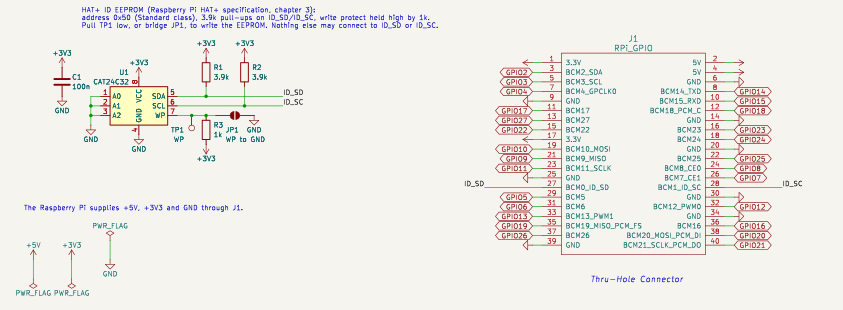
| Part | Value | Role |
|---|---|---|
| U1 | CAT24C32, SOIC-8 | The EEPROM: 32 Kb, 3.3 V, 16-bit addressing, write protect covering the whole array |
| R1, R2 | 3.9 kΩ | Pull-ups on ID_SD and ID_SC, the value the specification requires |
| R3 | 1 kΩ | Holds write protect high; stiff because the CAT24C32 pulls WP down internally |
| TP1 | Test point | Pull low to write the EEPROM during board test |
| JP1 | Solder jumper, open | Bridge to tie WP to GND, so a user can rewrite the EEPROM |
| C1 | 100 nF | Decoupling at U1's supply pins |
This follows the HAT+ specification, chapter 3 (it names the CAT24C32 as its recommended part), and the reference circuit in Raspberry Pi's HAT design guide. Another EEPROM must meet the specification's requirements: a 3.3 V 24Cxx part with 16-bit addressing, no clock stretching, not paged, and a write-protect pin that protects the whole array. Some Microchip variants fail the last one.
Address class
A0, A1 and A2 are tied low, so U1 answers at 0x50. HAT+ addresses take the
form 101_00XY, and the last two bits say what class of HAT+ the board is
(chapter 3.1):
| Address | A1 A0 | Class | For a board that… |
|---|---|---|---|
| 0x50 | 0 0 | Standard | uses the usual HAT pins, GPIOs 2 to 27 (the template's default) |
| 0x51 | 0 1 | Stackable | uses only the ID pins, not GPIOs 2 to 27 |
| 0x52 | 1 0 | Power, MODE0 | powers the Pi but not its peripherals (about 3 A); no GPIOs 2 to 27 |
| 0x53 | 1 1 | Power, MODE1 | powers the Pi and its peripherals (about 5 A); no GPIOs 2 to 27 |
One HAT+ of each class can share a Pi. To change class, tie A0 or A1 to +3V3 instead of GND.
Programming it
The tools are eeptools in Raspberry Pi's
utils repository;
the specification's appendix B is the full procedure. In outline:
- Build and install
eeptoolson a Pi (it needscmake). - Copy its
eeprom_settings.txttemplate, fill in your vendor, product and overlay name, and build the image witheepmake. Keep the product UUID it generates in your settings file, so later images keep the same one. - Make the EEPROM writable: hold TP1 low, or bridge JP1.
- Load a software I²C bus on the ID pins (
dtoverlay i2c-gpioon GPIO 0 and 1), check the EEPROM answers at 0x50 withi2cdetect, and write the image witheepflash.sh, naming the24c32type. - Make it read-only again: release TP1, or clear JP1.
Leave JP1 open on boards you ship, so the contents stay locked until someone chooses to change them.