Getting started
Install
The library is not in the Arduino Library Manager or the PlatformIO registry yet. Until it is, install it from a release:
- Download the source
.zipof the latest release. - In the Arduino IDE, choose Sketch → Include Library → Add .ZIP Library… and pick the file.
Or clone the repository into your Arduino libraries folder:
git clone https://github.com/CameronBrooks11/mq-gas-sensor
It builds for AVR boards, the ESP32 and the ESP8266.
Wire the sensor
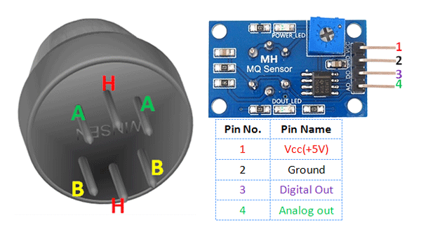
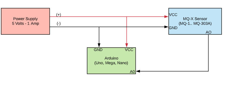
Most MQ sensors come on a module with four pins. The library reads the analog one.
| Module pin | Connect to |
|---|---|
| VCC | 5 V |
| GND | GND |
| AO | an analog input, such as A0 |
| DO | not used by the library; it is the module's comparator output (Digital_Input reads it) |
3.3 V boards
The sensor's output can reach its 5 V supply. On an ESP32 or ESP8266, divide it down before it reaches the analog pin. Sensors shows the wiring.
The MQ-7 and MQ-309A need their heater switched between two voltages; see Sensors.
The measurement
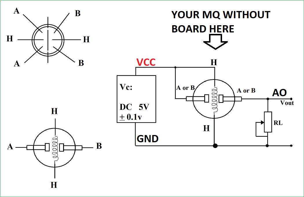
The sensor's resistance Rs changes with the concentration of the gases it detects; for most of them it falls as the gas rises. On the module, Rs sits in series with a load resistor RL, and the analog pin reads the voltage across RL:
Rs = (Vsupply × RL / Vout) − RL
Datasheets plot the ratio Rs/R0 against concentration, where R0 is the sensor's resistance in a reference condition, usually clean air. The library fits that plot with a curve, by default a power law:
ppm = a × (Rs/R0)^b
So a reading needs three things: the circuit (RL and the voltages), R0, and the curve (a and b).
Set up the circuit
MQGasSensor MQ2(A0, 5.0, 10, "MQ-2"); // analog pin, ADC reference (V), ADC bits, name
The ADC reference and resolution turn the raw reading into volts: 5.0 V and 10 bits on an Uno, Nano or Mega; 3.3 V and 12 bits on an ESP32; 3.3 V and 10 bits on an ESP8266.
Rs depends only on the supply voltage divided by the output voltage, so the two must be on the same scale. The supply defaults to the ADC reference, which is right in the two usual cases: a 5 V board reading a 5 V sensor directly, and a 3.3 V board reading a 5 V sensor through a divider that scales 5 V down to 3.3 V, as in the ESP wiring. Otherwise, give the supply in the same terms as the voltage the library is given. An external ADC that reports the sensor's true output, such as the ADS1115 in MQ135-ADS1115, needs the true supply:
MQ135.setSupplyVoltage(5.0); // voltages from updateFromVoltage() are unscaled
RL defaults to 10 kΩ. Modules differ, so read it off yours (an SMD resistor marked 102 is 1 kΩ, 103 is 10 kΩ) and set it if it is not 10 kΩ:
MQ2.setLoadResistance(1.0); // kΩ
Choose a curve
Pick the gas from Calibration coefficients and pass its a and b:
MQ2.setCurve(564.77, -2.151); // LPG
To read several gases from one sensor, call setCurve before each readPpm, as MQ-135-ALL does.
Calibrate R0
R0 is measured once, in clean air, after the heater has run for the warm-up time its datasheet gives. calibrate takes the datasheet's Rs/R0 in clean air, from the Clean air table, measures Rs, and stores R0 = Rs / that ratio:
MQ2.update();
float r0 = MQ2.calibrate(9.51); // MQ-2: Rs/R0 is 9.51 in clean air
Averaging several readings gives a steadier R0, as the examples do. Store the value, for example in EEPROM, and load it with setR0(r0) on later starts instead of recalibrating every time. The Calibration sketch prints R0 continuously so you can watch it settle.
The examples stop with a warning when calibration gives one of two impossible values:
- R0 is infinite: the output read exactly 0 V, so no current flows through the sensor. It is unpowered, its sensing element is open, or AO is shorted to GND. A disconnected AO wire can float instead, giving readings that wander rather than a clean 0, so a wandering R0 points at the wiring too.
- R0 is zero: the output read at or above the supply voltage, which only a sensor with no resistance would give. Either the reading clipped at the top of the ADC's range, as a 5 V output on a 3.3 V input without a divider does; or the supply voltage does not match the scale the output was measured on (Set up the circuit); or AO is shorted to VCC.
Read
void loop() {
  if (MQ2.update()) {           // false if the pin read 0 V
    float ppm = MQ2.readPpm();  // NAN if the last update read 0 V
    Serial.println(ppm);
  }
  delay(500);
}
printDebug() prints the whole chain in one line — voltage, Rs, R0, ratio, ppm and the curve — which is the quickest way to see which step is off.
Read from an external ADC
If another converter, such as an ADS1115, reads the sensor, pass its result instead of calling update(), and skip begin() so the library never touches the pin:
MQ135.updateFromVoltage(volts); // or updateFromRaw(raw) at the resolution given to the constructor