Workflow
A single file is enough for one view of one part. A real drawing has several views on a sheet with a title block, and it is easier to manage as four kinds of file. This is the layout the examples in the repository use.
| File | Holds |
|---|---|
| Config | The drawing settings: SCALING_FACTOR, colours, the annotation height |
| Part | The part’s dimensions as top-level variables, and the module for it |
| One per view | The part in one orientation, with that view’s annotations |
| Sheet | The views placed on a sheet, with the frame and title block |
The rest of this page builds a small drawing that way.
Config
// file: config.scad
DOC_HEIGHT = 3;
DOC_HEIGHT is your own variable, not the library’s. It is the height the annotations sit at, and it has to clear the tallest part in any view. Library settings such as SCALING_FACTOR go here too; see Configuration.
Part
// file: part.scad
plate_length = 4.5;
plate_width = 2;
plate_thickness = 0.2;
hole_x = 1;
hole_y = 1;
hole_r = 0.4;

module plate()
{
    difference()
    {
        cube([ plate_length, plate_width, plate_thickness ]);
        translate([ hole_x, hole_y, -1 ]) cylinder(h = 2, r = hole_r, $fn = 64);
    }
}
Keep every dimension as a named top-level variable. The view files read the same variables, so a dimension on the drawing cannot disagree with the part.
Views
// file: view_top.scad
include <config.scad>
include <DraftSCAD/dimdraft.scad>
include <part.scad>

module view_top()
{
    plate();

    translate([ 0, 0, DOC_HEIGHT ])
    {
        translate([ 0, plate_width + DIM_SPACE * 4, 0 ]) dimensions(plate_length);
        translate([ 0, plate_width + DIM_SPACE, 0 ]) line(length = DIM_SPACE * 4, vert = true);
        translate([ plate_length, plate_width + DIM_SPACE, 0 ]) line(length = DIM_SPACE * 4, vert = true);

        translate([ hole_x, hole_y, 0 ])
        {
            circle_center(radius = hole_r);
            leader_line(angle = -45, radius = hole_r, angle_length = 0.6, horz_length = 0.3, text = str("R ", hole_r));
        }
    }
}

view_top();
// file: view_front.scad
include <config.scad>
include <DraftSCAD/dimdraft.scad>
include <part.scad>

module view_front()
{
    // stand the plate on its long edge so the camera sees the front face
    translate([ 0, plate_thickness, 0 ]) rotate([ 90, 0, 0 ]) plate();

    translate([ 0, 0, DOC_HEIGHT ])
    {
        // thickness, drawn to the right of the view
        translate([ plate_length + DIM_SPACE * 3, 0, 0 ]) rotate([ 0, 0, 90 ])
            dimensions(plate_thickness, loc = DIM_RIGHT);
        translate([ plate_length + DIM_SPACE, 0, 0 ]) line(length = DIM_SPACE * 3);
        translate([ plate_length + DIM_SPACE, plate_thickness, 0 ]) line(length = DIM_SPACE * 3);
    }
}

view_front();
Each view file includes the config, the library and the part, in that order, and ends by calling its own module. That last line means you can open a view file on its own and work on it.
The config comes first because the library reads its settings when it is included.
A dimension is always drawn along X. For a vertical one, rotate it, as view_front does.
Sheet
// file: sheet.scad
include <config.scad>
include <DraftSCAD/ddtemplates.scad>
include <DraftSCAD/dimdraft.scad>

use <view_top.scad>
use <view_front.scad>

translate([ 1.5, 5.5, 0 ]) view_top();
translate([ 1.5, 4.2, 0 ]) view_front();

// the frame and grid sit just below the views
translate([ 0, 0, -DIM_LINE_WIDTH ]) draw_sheet(length = 11, height = 8.5, grid_type = "Dot", grid_dim = 0.5);

part_details = [ "Plate", "Aluminium", "None", "0.1", "P-001" ];
doc_details = [ "D-001", "A. Maker", "", "2026-01-01" ];
org_details = [ "", "My Workshop", "" ];
translate([ 3.7, 3.52, 0 ]) titleblock0(part_details, doc_details, org_details);
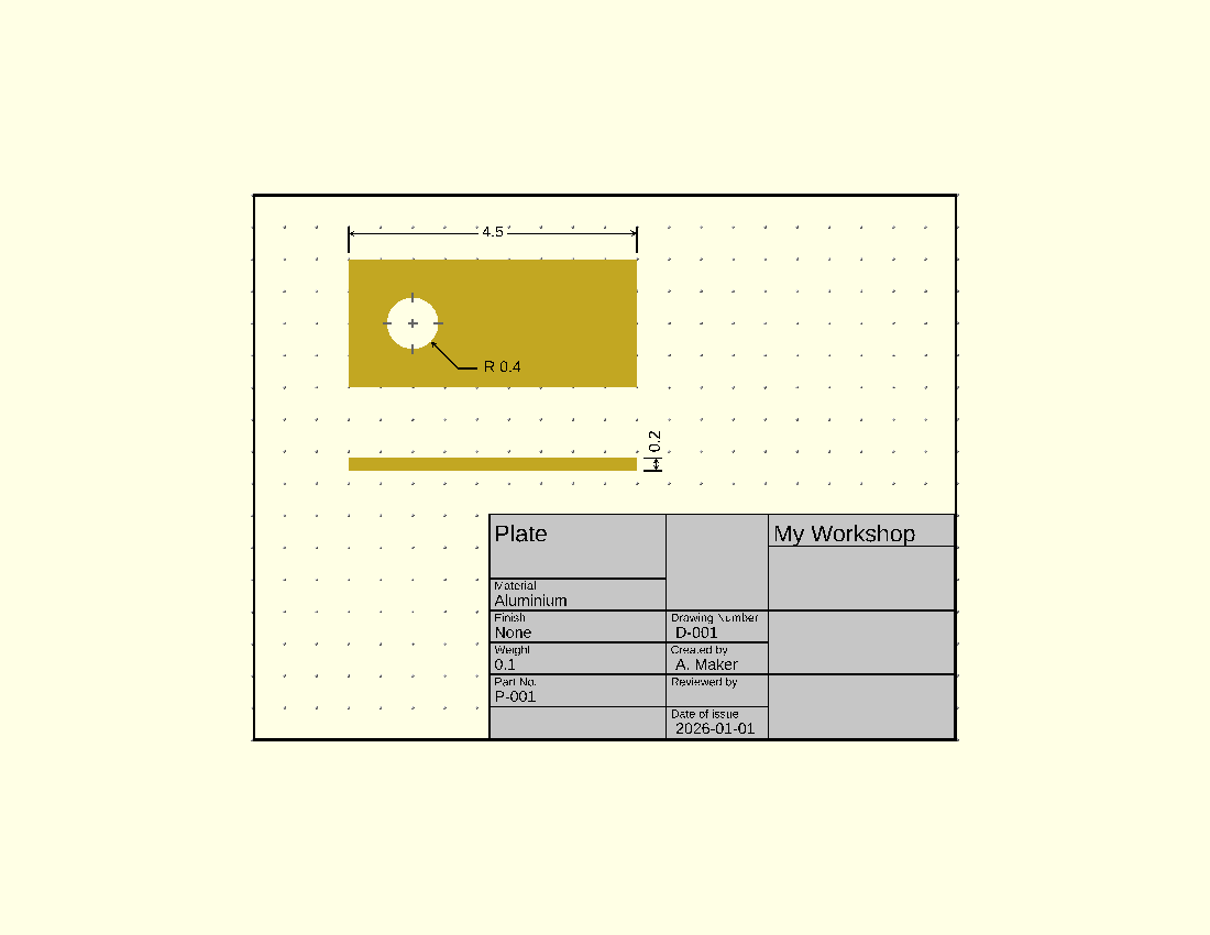
The sheet brings the views in with use, not include. use makes the module available without running the view_top(); call at the bottom of the view file, so each view appears once, where the sheet puts it.
The title block is placed by hand. Its origin is its top-left corner; see Title blocks for its size.
Sharing dimensions between parts
When two parts must agree on a dimension, such as a shaft and the hole it goes through, put that dimension in a file both parts include. Keep dimensions that belong to one part in that part’s file.
OpenSCAD has one namespace for top-level variables in included files, so give each a distinct name. Two included part files that both define length will silently share the last value assigned.