Lines and dimensions
Defined in src/dd_dimlines.scad.
line
line(length, width = DIM_LINE_WIDTH, height = DIM_LINE_HEIGHT, left_arrow = false, right_arrow = false,
     vert = false, color = DEF_LINE_COLOR)
Draws a straight line from the origin along +X, with an optional arrowhead at either end.
| Parameter | Meaning |
|---|---|
length | Total length, arrowheads included |
width | Line width |
height | Z thickness |
left_arrow | Arrowhead at the origin end |
right_arrow | Arrowhead at the far end |
vert | Draw along +Y instead of +X |
color | Line colour |
The line starts at the origin and is centred on its axis across its width. That makes a line easy to place by its start point, and lets two lines meet at a corner without a half-width correction.
An arrowhead is 4 line widths across.
include <DraftSCAD/dimdraft.scad>

line(length = 2);
translate([ 0, -0.3, 0 ]) line(length = 2, left_arrow = true);
translate([ 0, -0.6, 0 ]) line(length = 2, right_arrow = true);
translate([ 0, -0.9, 0 ]) line(length = 2, left_arrow = true, right_arrow = true);
translate([ 2.5, -0.9, 0 ]) line(length = 0.9, vert = true);
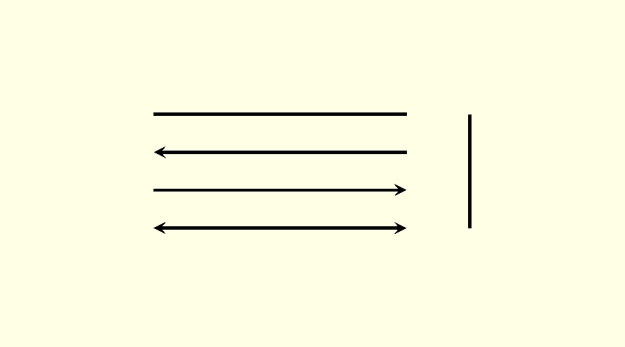
arrow
arrow(arr_points, arr_length, height, color = DEF_LINE_COLOR)
Draws one arrowhead with its tip at the origin, pointing toward −X. line() uses it; you rarely need it directly.
| Parameter | Meaning |
|---|---|
arr_points | Width across the barbs, and the distance from tip to barbs |
arr_length | Distance from the tip to the notch at the back of the head |
height | Z thickness |
dimensions
dimensions(length, line_width = DIM_LINE_WIDTH, line_height = DIM_LINE_HEIGHT, loc = DIM_CENTER,
           color = DEF_LINE_COLOR, text_color = DEF_TEXT_COLOR)
Draws a dimension line from the origin along +X, length long, labelled with length.
| Parameter | Meaning |
|---|---|
length | The distance to dimension, and the label |
loc | Where the label goes; see below |
loc | Result |
|---|---|
DIM_CENTER | Arrows point outward to both ends, with the label in a gap in the middle |
DIM_LEFT | One unbroken line with an arrow at each end, label to the left |
DIM_RIGHT | One unbroken line with an arrow at each end, label to the right |
DIM_OUTSIDE | Two arrows outside the distance pointing inward, label between them |
Use DIM_LEFT, DIM_RIGHT or DIM_OUTSIDE when the distance is too short to hold the label.
If you do not, the module handles it. A DIM_CENTER dimension with no room for its label and two arrows is drawn in the DIM_OUTSIDE form. If the label does not fit between the arrows either, it goes to the right of them.
include <DraftSCAD/dimdraft.scad>

length = 2.5;

// two vertical lines to mark the distance being dimensioned
line(length = 2.2, vert = true);
translate([ length, 0, 0 ]) line(length = 2.2, vert = true);

locs = [ DIM_CENTER, DIM_LEFT, DIM_RIGHT, DIM_OUTSIDE ];
for (i = [0:3])
    translate([ 0, 0.3 + 0.5 * i, 0 ]) dimensions(length, loc = locs[i]);
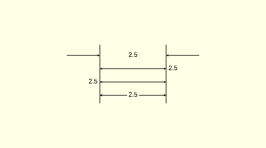
Things to know:
- The label is always
str(length). There is no way to add a prefix, a tolerance or units, or to set the precision. - A dimension is always horizontal. For a vertical one, wrap it in
rotate([ 0, 0, 90 ]); the label rotates with it. - The module does not draw extension lines. Draw those with
line(). - The room a label needs comes from
dd_text_units(), an estimate that is exact for numbers in the default font.
dd_text_units
dd_text_units(text)
A function. It estimates the width of a string in font units, at OpenSCAD’s default text size of 10. Multiply by DIM_FONTSCALE for the width as drawn.
It counts 7.724 for every character except a period or a space, which count 3.859. Those are the advances of the digits, the period and the space in the default font, so the result is exact for a number: dd_text_units("3.53") is 27.031. It is only approximate for letters, which vary in width, and for any other font.
The library estimates the width and does not call textmetrics(), so it needs nothing newer than OpenSCAD 2021.01.
leader_line
leader_line(angle, radius, angle_length, horz_length, direction = DIM_RIGHT, line_width = DIM_LINE_WIDTH,
            line_height = DIM_LINE_HEIGHT, text = "", do_circle = false, color = DEF_LINE_COLOR,
            text_color = DEF_TEXT_COLOR)
Draws an arrow pointing at the origin from a given angle, a horizontal shoulder, and a label.
| Parameter | Meaning |
|---|---|
angle | Direction of the angled segment, in degrees from +X |
radius | Distance from the origin to the arrow tip |
angle_length | Length of the angled segment |
horz_length | Length of the horizontal shoulder |
direction | DIM_RIGHT or DIM_LEFT: which way the shoulder and label extend |
text | The label; leave it out to draw the line alone |
do_circle | Draw a circle around the label, for a balloon number |
Translate to the centre of the feature first. To point at the rim of a hole, pass the hole’s radius as radius. To point at a spot, pass radius = 0.
include <DraftSCAD/dimdraft.scad>

radius = 0.5;
circle_center(radius);

leader_line(angle = 30, radius = radius, angle_length = 0.75, horz_length = 0.5, text = "to the right");
leader_line(angle = 150, radius = radius, angle_length = 0.75, horz_length = 0.5, direction = DIM_LEFT,
            text = "to the left");
leader_line(angle = -45, radius = radius, angle_length = 1, horz_length = 0.25, text = "1", do_circle = true);
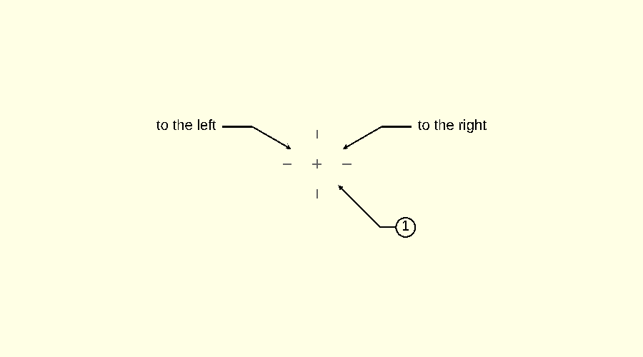
The circle is centred on the label and its edge meets the end of the shoulder line. Its size comes from dd_text_units(), so it fits a number; a label of letters may sit off-centre in it.
circle_center
circle_center(radius, size = DIM_HOLE_CENTER, line_width = DIM_LINE_WIDTH, line_height = DIM_LINE_HEIGHT,
              color = "grey")
Marks the centre of a circle at the origin: a cross at the centre, and a short tick across the circle on each axis.
| Parameter | Meaning |
|---|---|
radius | Radius of the circle being marked |
size | Length of each mark |
include <DraftSCAD/dimdraft.scad>

radius = 0.5;

difference()
{
    cube([ 2, 2, 1 ], center = true);
    cylinder(h = 2, r = radius, center = true, $fn = 100);
}

// drawn just above the top face
translate([ 0, 0, 0.5 ]) circle_center(radius);
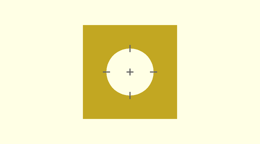
The module does not draw centre lines across the part. Add those with line() if you want them.