Getting started
Install
Clone the repository into your OpenSCAD library folder. In OpenSCAD, File → Show Library Folder opens it.
git clone https://github.com/CameronBrooks11/DraftSCAD.git
You can also clone it next to your project and include it by relative path.
DraftSCAD is developed against OpenSCAD 2026.10.15. The examples are also evaluated on the 2021.01 release in CI.
Include the library
include <DraftSCAD/dimdraft.scad>
Use include, not use. The library’s constants, such as DIM_LEFT and DIM_SPACE, are top-level variables, and use does not bring those into your file.
The title block templates are a second file:
include <DraftSCAD/ddtemplates.scad>
A first drawing
This models a plate with one hole and dimensions it.
include <DraftSCAD/dimdraft.scad>

plate = [ 4.5, 2, 0.2 ];
hole_pos = [ 1, 1 ];
hole_r = 0.4;

// the part
difference()
{
    cube(plate);
    translate([ hole_pos[0], hole_pos[1], -1 ]) cylinder(h = 2, r = hole_r, $fn = 64);
}

// the annotations, on a plane above the part
translate([ 0, 0, 1 ])
{
    // overall length, with an extension line at each end
    translate([ 0, plate[1] + DIM_SPACE * 4, 0 ]) dimensions(plate[0]);
    translate([ 0, plate[1] + DIM_SPACE, 0 ]) line(length = DIM_SPACE * 4, vert = true);
    translate([ plate[0], plate[1] + DIM_SPACE, 0 ]) line(length = DIM_SPACE * 4, vert = true);

    // the hole: centre marks and a leader with its radius
    translate([ hole_pos[0], hole_pos[1], 0 ])
    {
        circle_center(radius = hole_r);
        leader_line(angle = -45, radius = hole_r, angle_length = 0.6, horz_length = 0.3, text = str("R ", hole_r));
    }
}
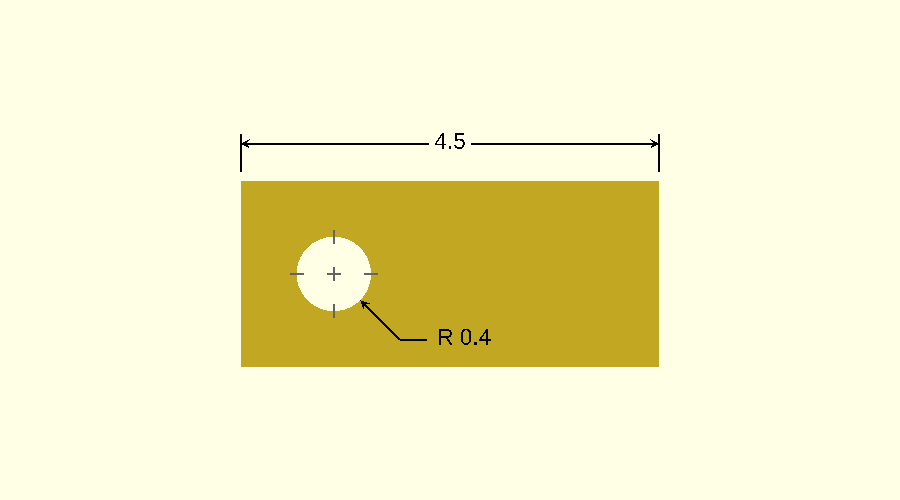
Three things to notice:
- The annotations are translated up by 1, above the top of the part. From the top they overlay it.
- Positions are written in multiples of
DIM_SPACE, the library’s spacing unit, so they follow the drawing scale. dimensions()prints the length it is given. The label is alwaysstr(length).
View it
- Preview with F5. Do not render with F6: the text disappears.
- View → Top.
- View → Orthogonal.
Export the drawing
In the application, File → Export → Export as Image saves the preview.
From the command line, this is the command that produced the image above:
openscad -o drawing.png --camera=0,0,0,0,0,0,0 --viewall --autocenter --projection=o --imgsize=900,500 drawing.scad
--camera=0,0,0,0,0,0,0 looks straight down, --projection=o is orthogonal, and --viewall --autocenter fit the scene to the image.
There is no vector output. SVG, DXF and PDF export need a 2D scene, and a DraftSCAD drawing is 3D.
Scale
The default line width and text size suit a part a few units across, like the plate above. For a part hundreds of units across the annotations would be too small to see. Set SCALING_FACTOR before the include:
SCALING_FACTOR = 100;
include <DraftSCAD/dimdraft.scad>
Configuration covers this and the other settings.