Building the M12864 Transistor Tester — Step-by-Step Guide
A complete, beginner-friendly walkthrough for assembling the M12864 DIY transistor tester kit. If you’ve never soldered a through-hole kit before, don’t worry — this guide explains each step, the order to install parts, and what a good solder joint looks like.
When it’s finished, this little device measures transistors, MOSFETs, diodes, resistors, capacitors, and inductors all on its own, showing the results on an LCD. You just drop a component into the test socket and press the button.
Time: ~1–2 hours · Difficulty: beginner (basic soldering) · Cost: low
What you need
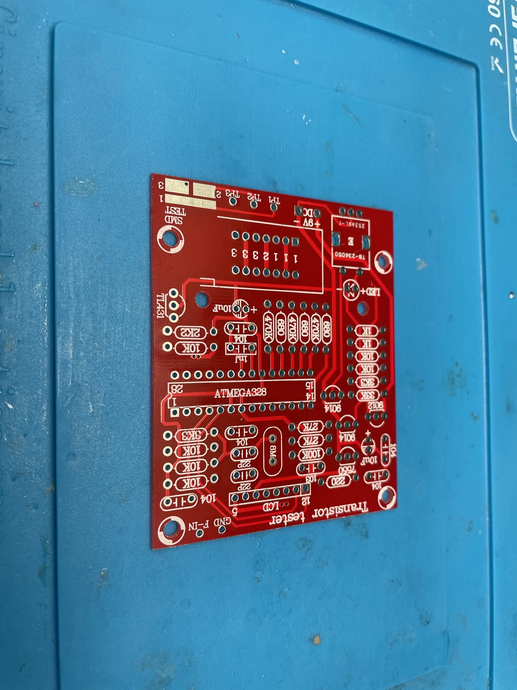
In the kit
- The red “Transistor tester” PCB (ATMEGA328 + 8 MHz crystal)
- Resistors — ten values: 220 Ω, 680 Ω, 1.0 kΩ, 2.2 kΩ, 3.3 kΩ, 10 kΩ, 27 kΩ, 33 kΩ, 100 kΩ, 470 kΩ
- Capacitors — ceramic (marked
104= 0.1 µF,1nJ,22p) and electrolytic (10 µF) - Semiconductors —
HT7550regulator,TL431voltage reference,9012/9014reference transistors ATMEGA328microcontroller (28-pin DIP) + its socket- ZIF test socket (the lever-locked socket components are inserted into)
- Contrast trimpot, LED, pin headers
- LCD display module (on a 20-pin header)
- 9 V battery clip
Tools you supply
- Soldering iron (a basic one like the Spurtar #160 shown here is fine) + solder
- Flush cutters (for trimming leads)
- Tip cleaner — brass wool or a damp sponge
- A 9 V battery for testing
- Optional: a multimeter to check your work
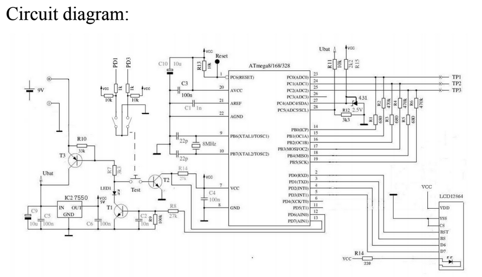
The circuit: here’s the full schematic if you’d like to follow along electrically.
💡 Golden rule of through-hole assembly: install parts from shortest to tallest. Resistors lie flat, so they go first; the LCD and battery clip go last. That way the board always rests flat while you solder.
⚠️ Safety & solder: the iron tip reaches 300+ °C / 600+ °F — park it in its stand, never on the bench. Work in a ventilated area and don’t breathe the flux smoke; wash your hands after handling solder. For a first build, leaded (60/40 or 63/37) rosin-core solder is the most forgiving to learn on — it melts cooler and flows more easily than lead-free.
1. Inventory & setup
Before melting any solder, lay everything out and confirm you have all the parts. Sorting the resistors now will save you a lot of squinting later.
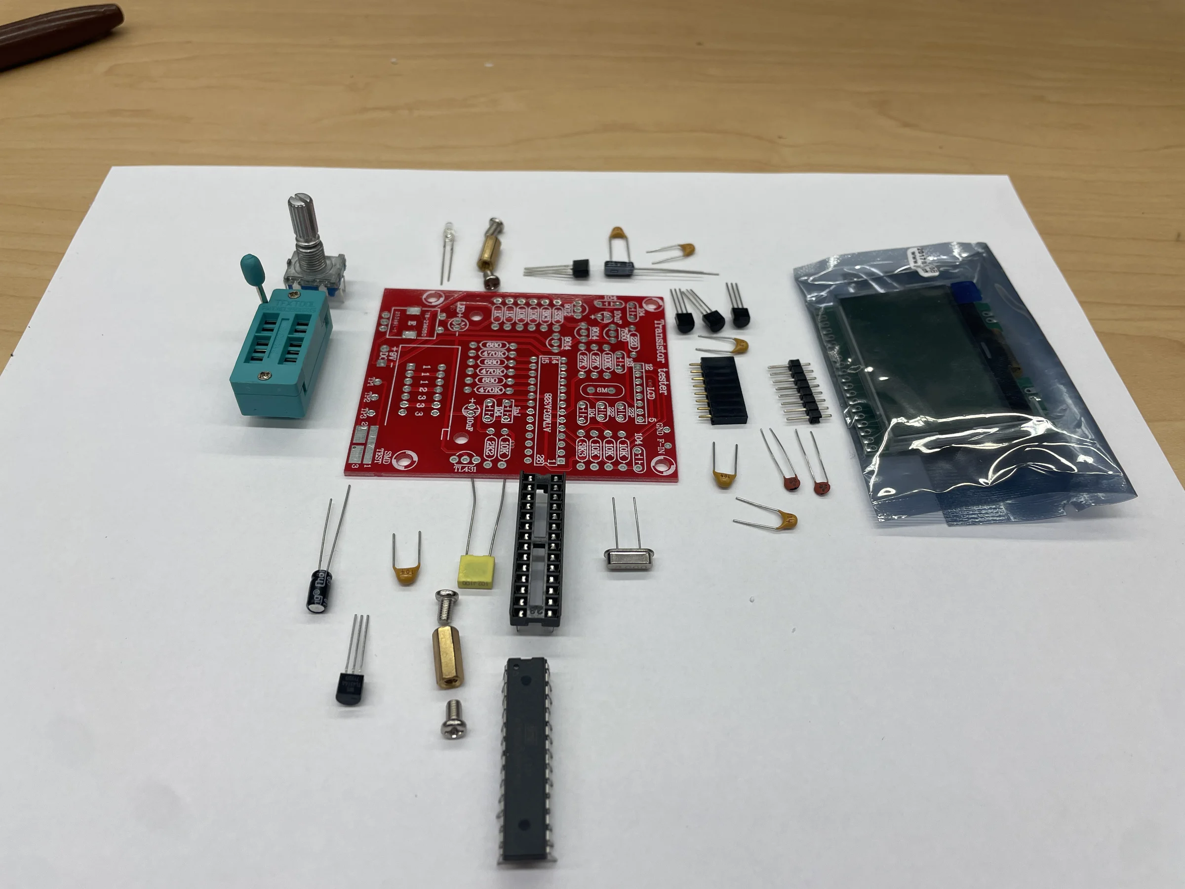
Sort your resistors. Resistors are labeled with colored bands, not numbers, so they’re easy to mix up. A simple trick: draw a grid on a sheet of paper, label each cell with a value, and lay each resistor in its box as you identify it. (Use a multimeter or an online resistor color-code calculator to read them.)
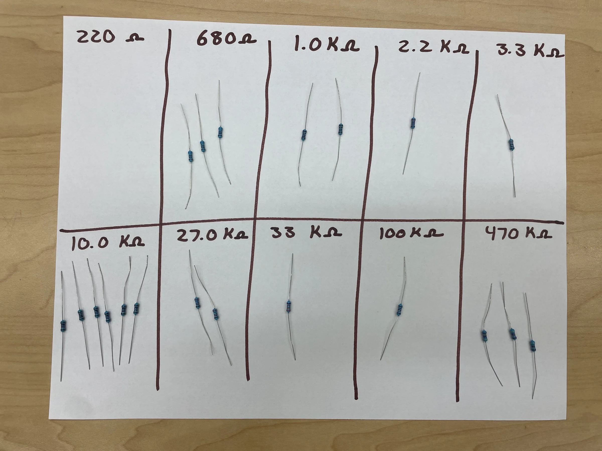
Inspect the bare board. The top (component) side has white silkscreen showing where every part goes and its value. The bottom (solder) side is where you’ll apply the iron.
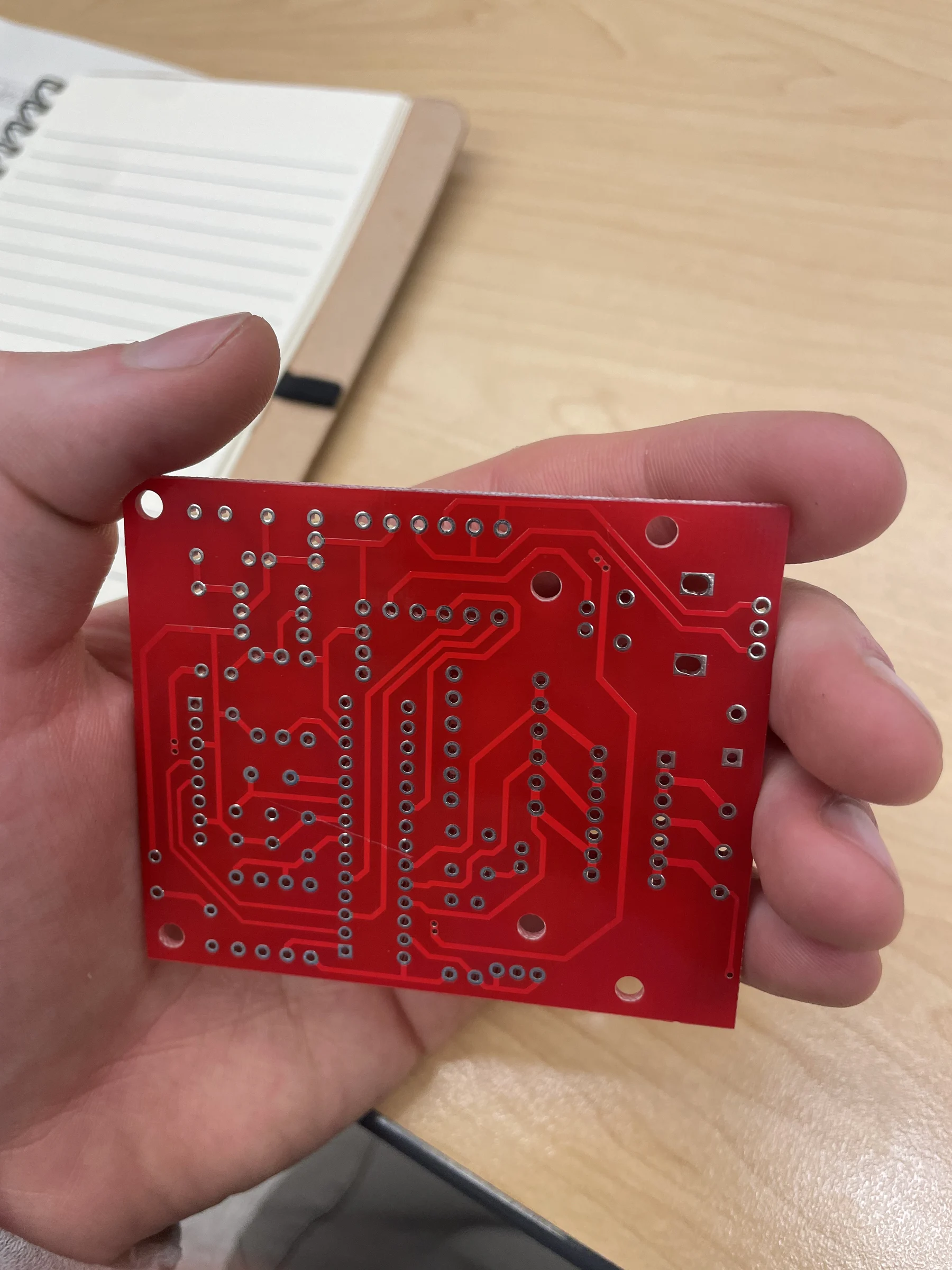
2. Get your iron ready
Good joints start with a clean, tinned tip. Let the iron come fully up to temperature, wipe the tip on brass wool (or a damp sponge), then melt a little solder onto it until it’s shiny — that’s “tinning.”
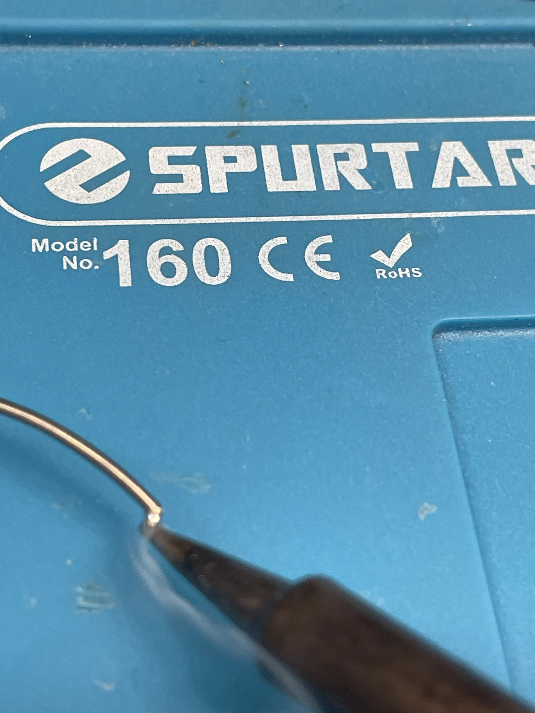
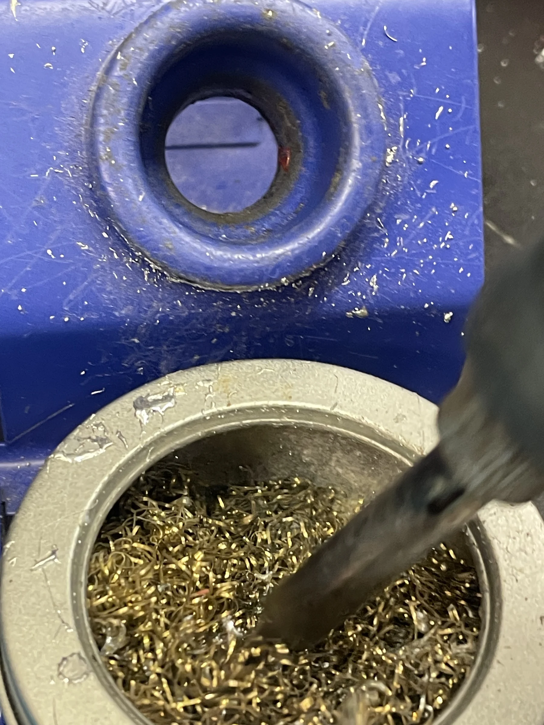
A clean, pointed tip transfers heat well and makes soldering much easier:
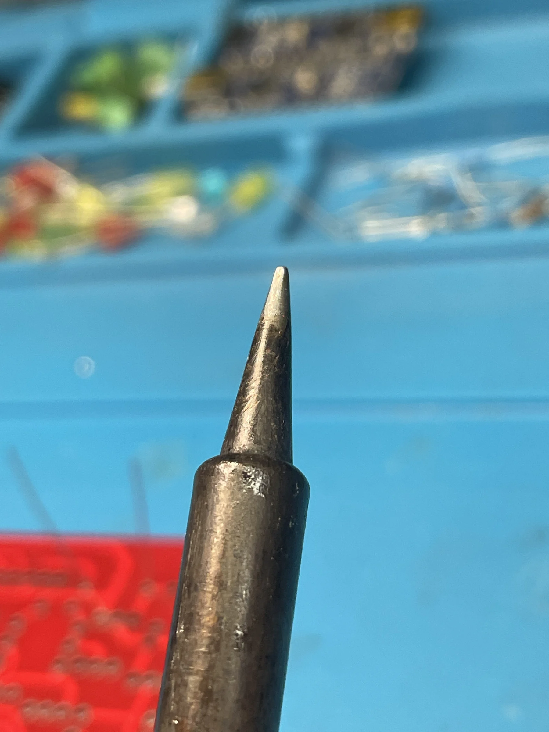
🔥 Never leave the iron on while idle. Turn it off (or drop it to standby) any time you’re not soldering for more than a minute or so — and always when you walk away from your station. Besides the fire/burn risk, a hot tip sitting idle oxidizes, and an oxidized tip transfers heat poorly, which quietly ruins your joints. If a tip does dull or discolor, revive it: melt fresh solder onto it, then wipe it on brass wool or a damp sponge — repeat until it’s shiny again.
3. How to solder one joint
Let’s do a single joint start to finish, so the rest of the build is just repetition.
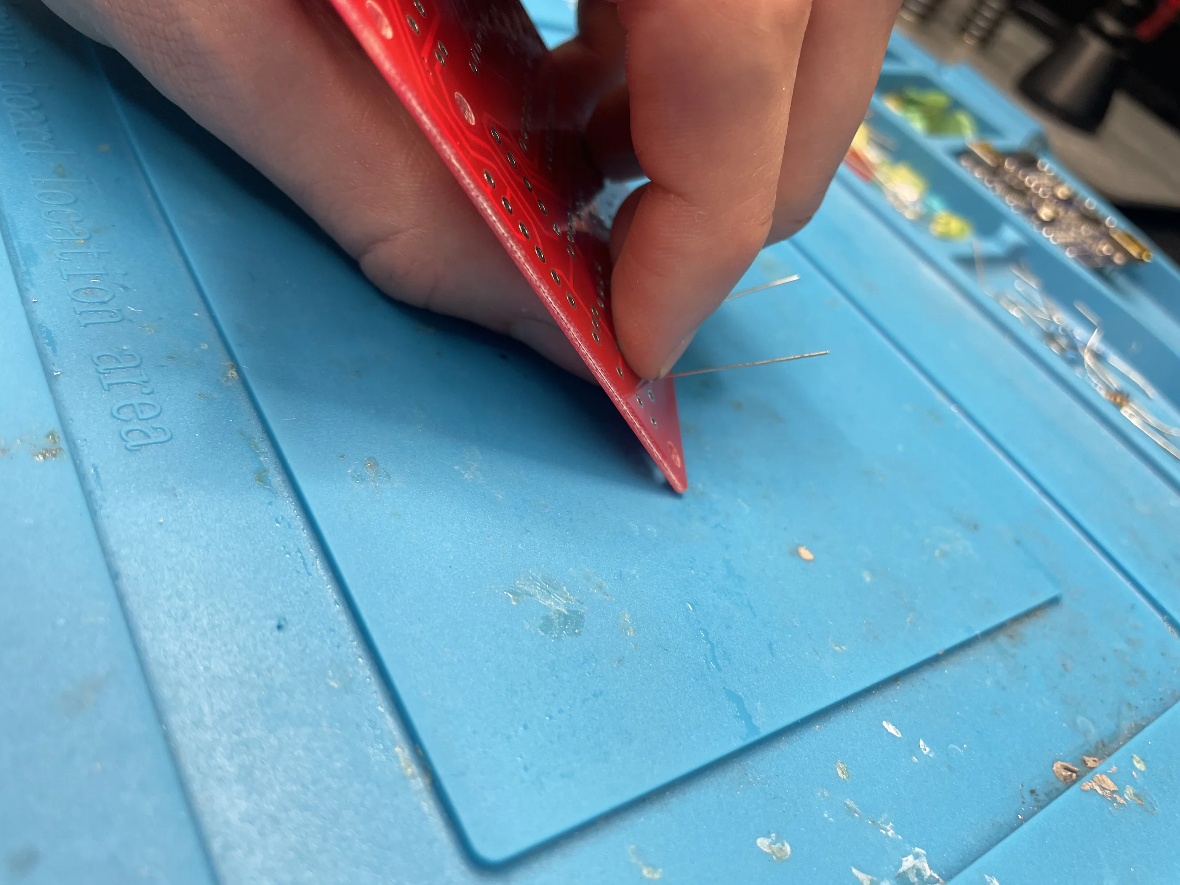
1. Prep & insert the part. Bend the leads to fit the footprint and push it through from the top side so it sits flat against the board.
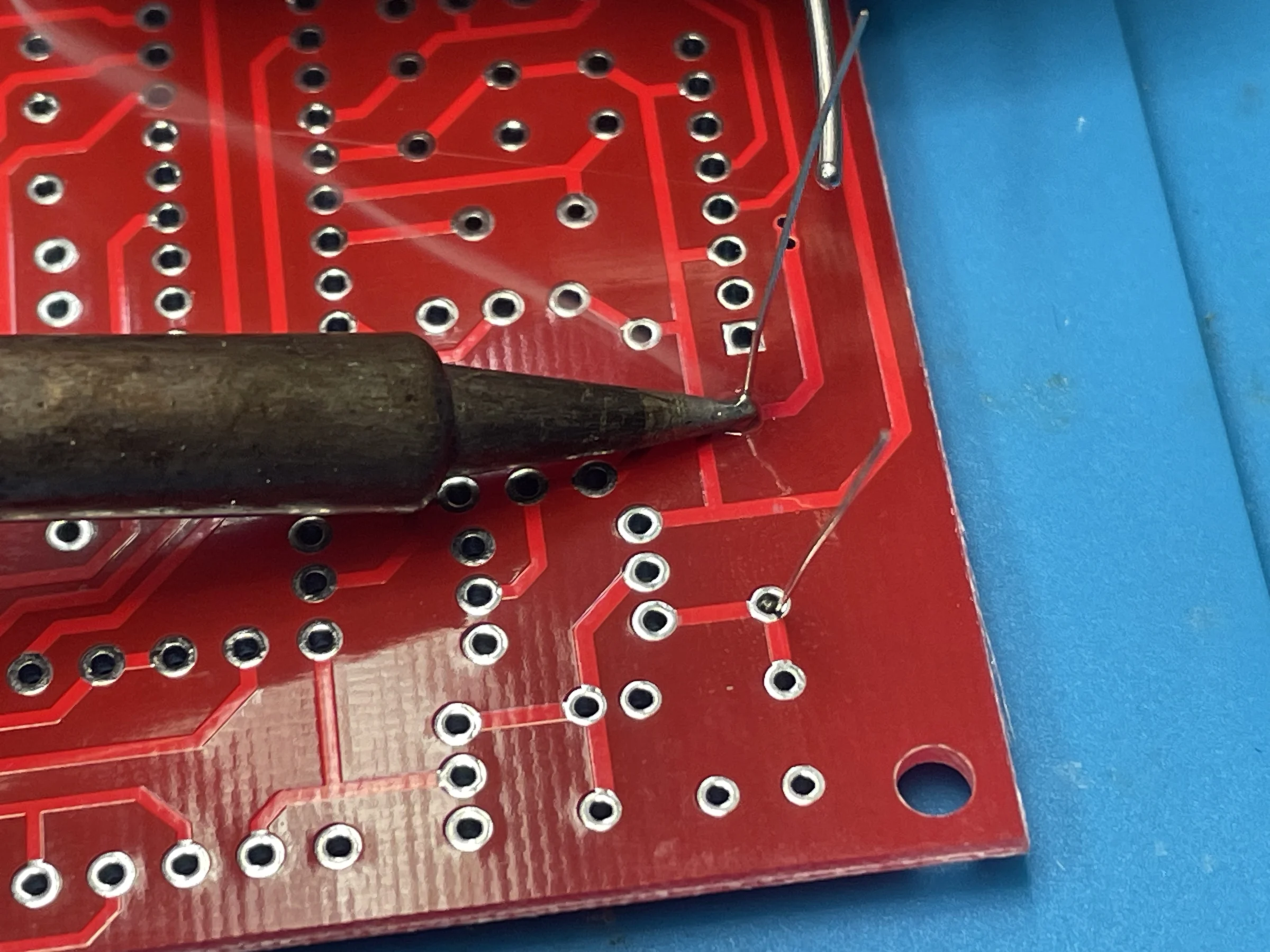
2. Heat both pad and lead. Flip the board over. Touch the iron tip to the pad and the lead at the same time for a second, then feed solder into the joint (not onto the iron). It should flow in and form a small shiny cone.
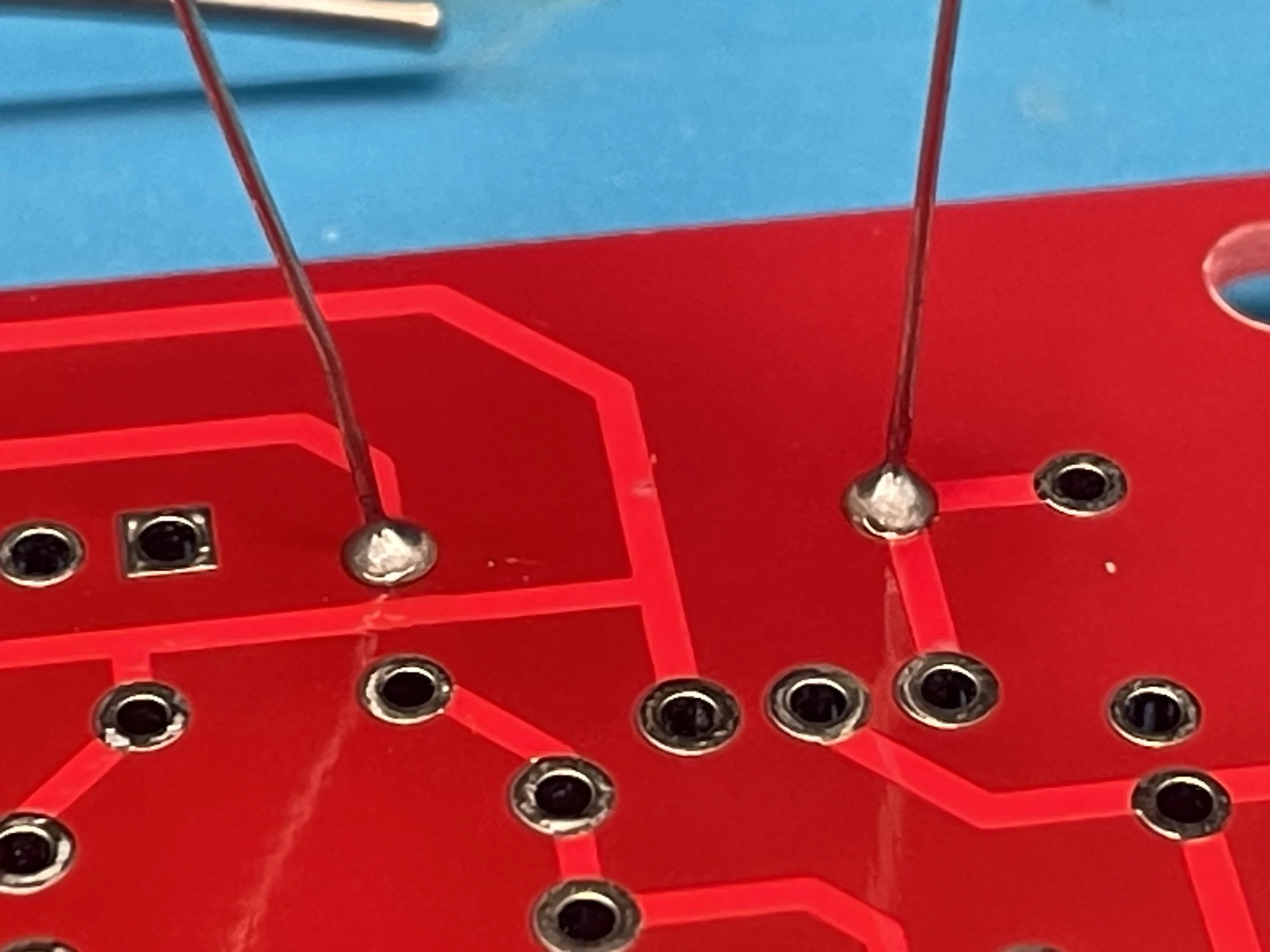
3. Check the joint. A good joint is smooth and shiny and shaped like a little volcano around the lead — not a dull ball.
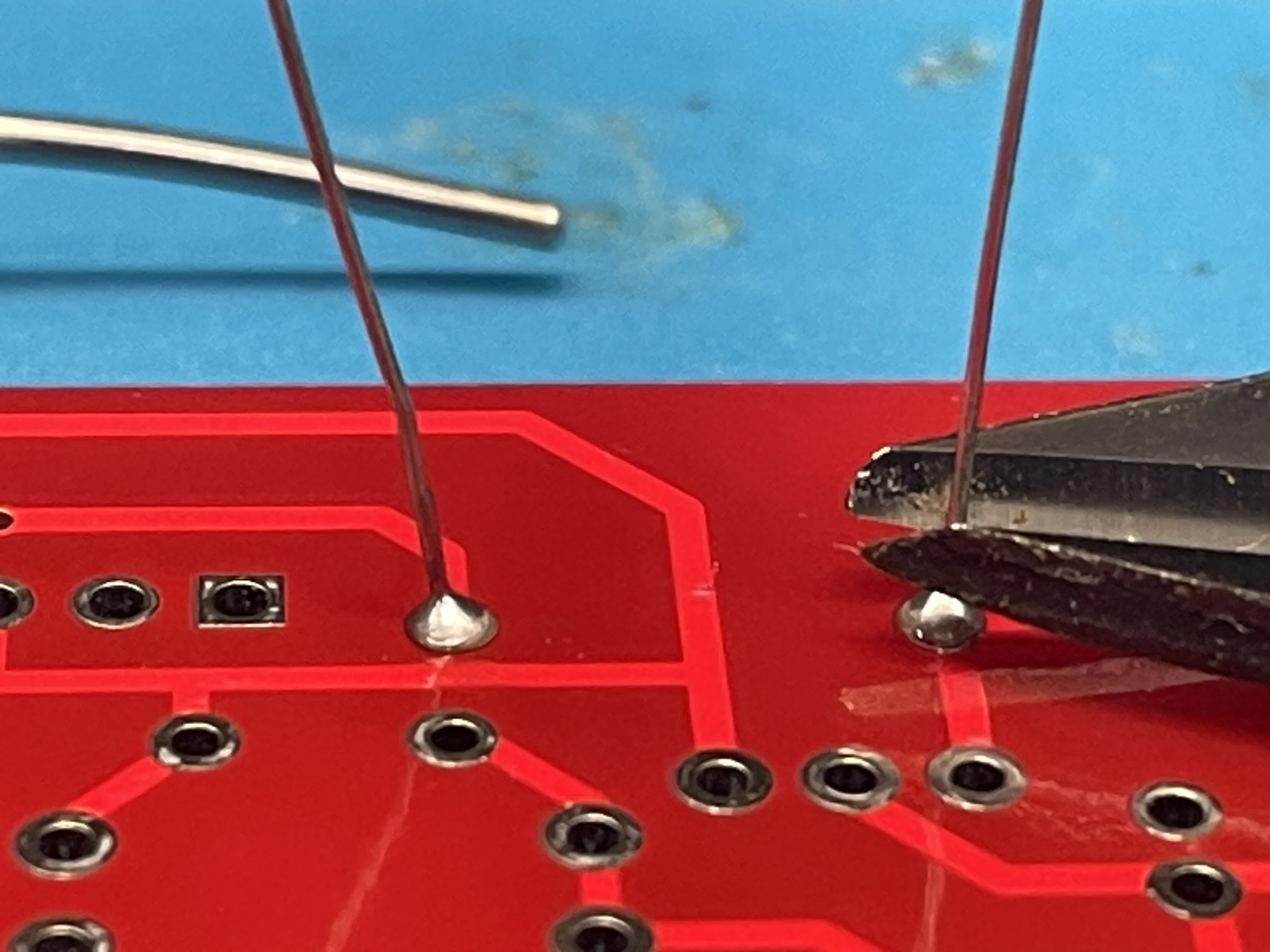
4. Trim the lead. Snip the excess lead flush with the top of the joint.
🔁 That’s the whole technique. Every part from here is: insert → solder → trim.
What a good joint looks like
A good joint is shiny, smooth, and concave — a small “volcano” fillet wetting both the pad and the lead. If a joint isn’t shiny and smooth, just reheat it; most kit problems come down to one bad joint.
| Joint | Looks like | Fix |
|---|---|---|
| ✅ Good | Shiny, smooth, concave fillet wetting both pad and lead | — |
| ❌ Cold joint | Dull, grainy, or lumpy; doesn’t wet the pad | Reheat until it flows and stays shiny |
| ❌ Insufficient solder | Thin, no fillet; lead barely covered | Add a touch more solder |
| ❌ Too much solder | A round ball; can hide a bad connection | Reheat and wick a little away |
| ❌ Solder bridge | Solder connecting two pads that shouldn’t touch | Remove with solder wick / desoldering braid |
| ❌ Disturbed joint | Cracked or frosty (moved while cooling) | Reheat and hold still while it sets |
Hold each part still for a second after pulling the iron away — moving a joint while it solidifies is what creates a cold joint. A joint usually needs only 2–3 seconds of heat.
4. Install the resistors
Resistors are flat and heat-tolerant, so they go first. Work across the board, matching each resistor to its printed value on the silkscreen. Your sorting sheet from Step 1 is your cheat sheet here.
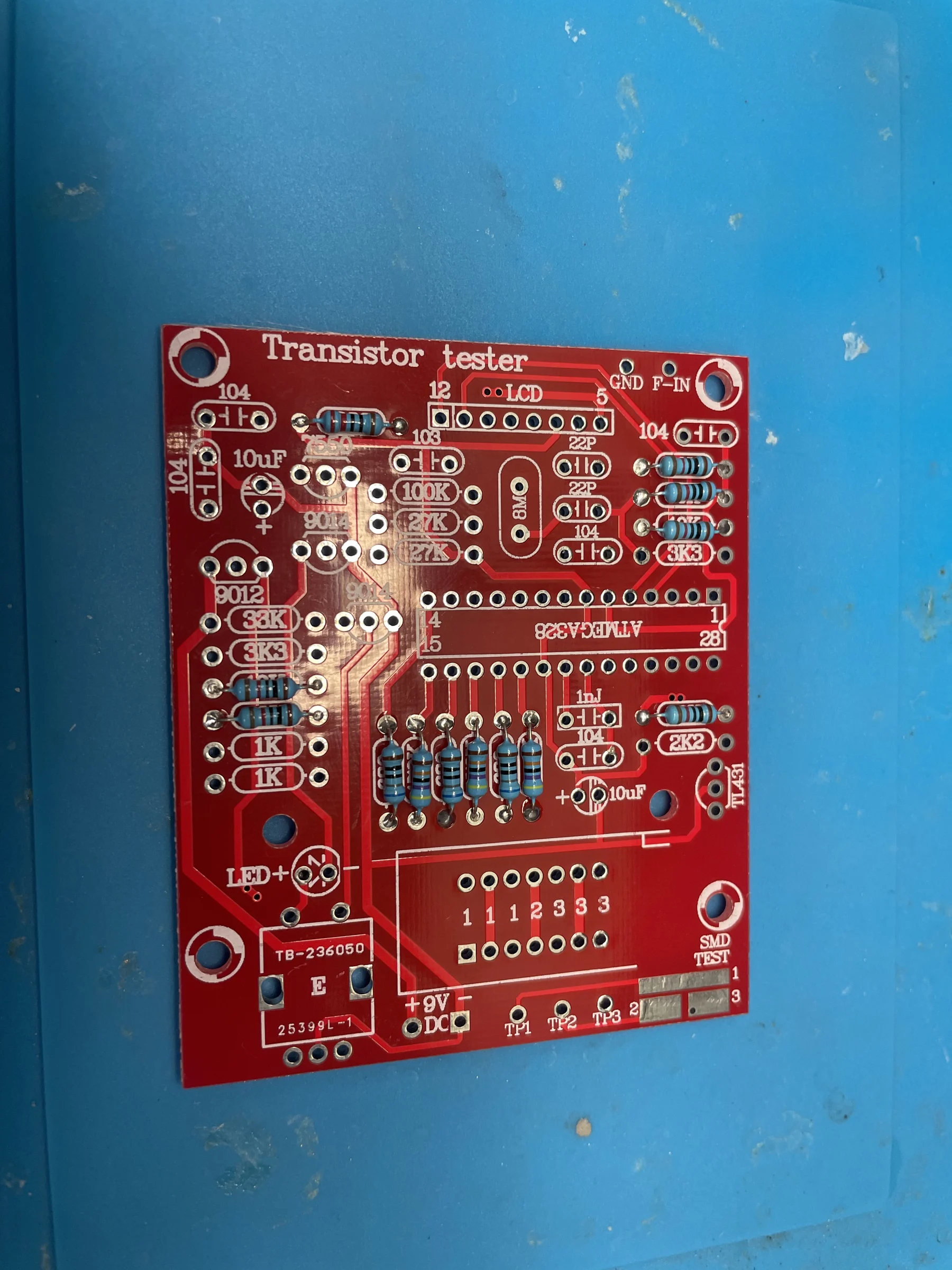
A handy method: insert a few resistors, bend their leads slightly outward on the back to hold them, then flip the board and solder them all at once. Repeat until every resistor position is filled.
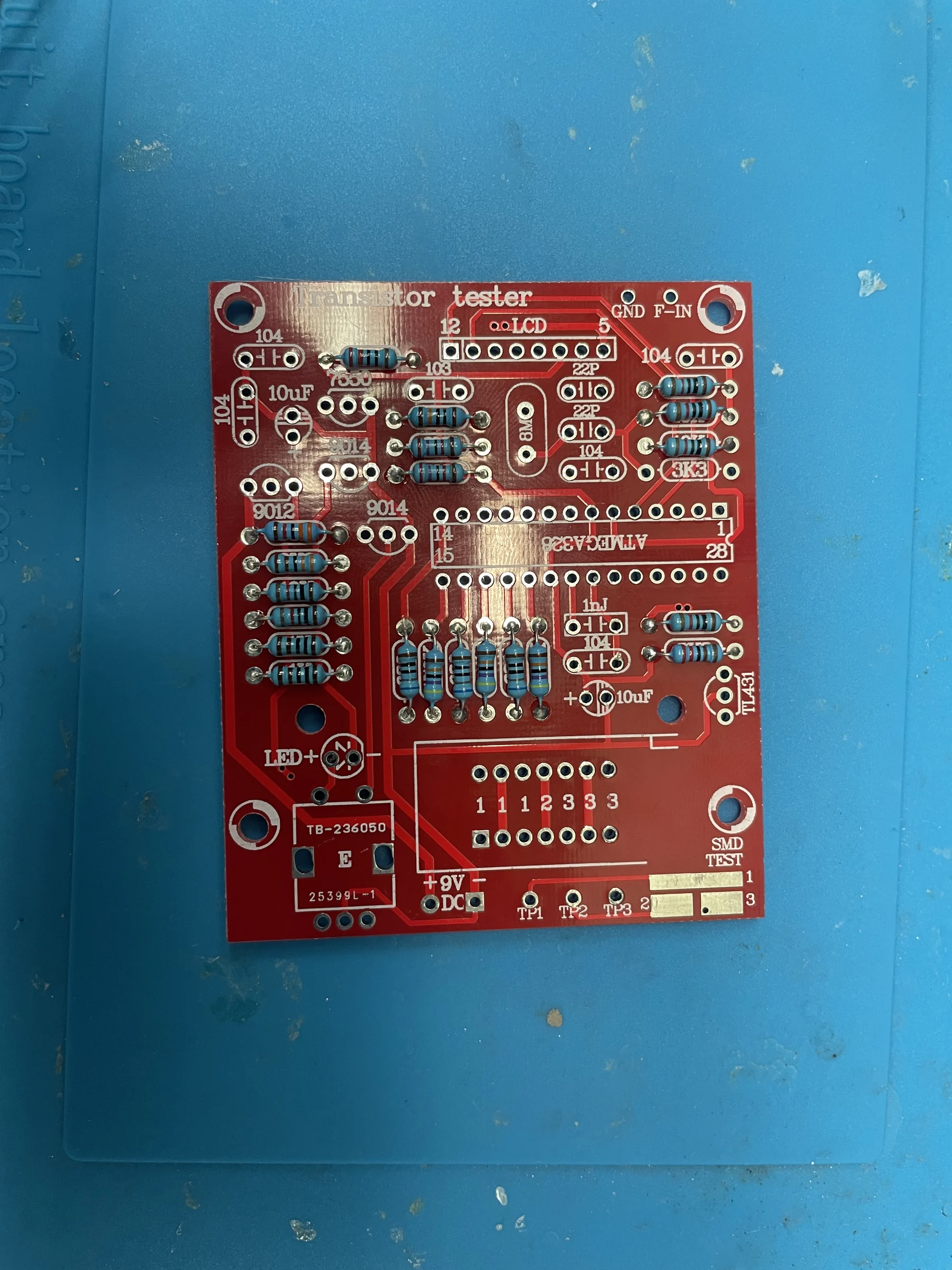
5. Install the capacitors & small parts
With the resistors in, set out the remaining parts so you can see what’s left.
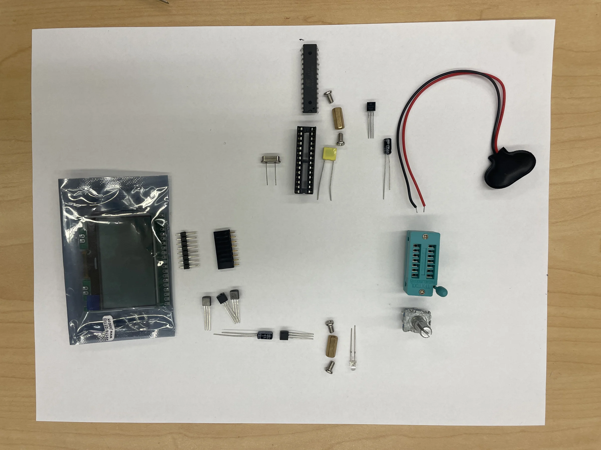
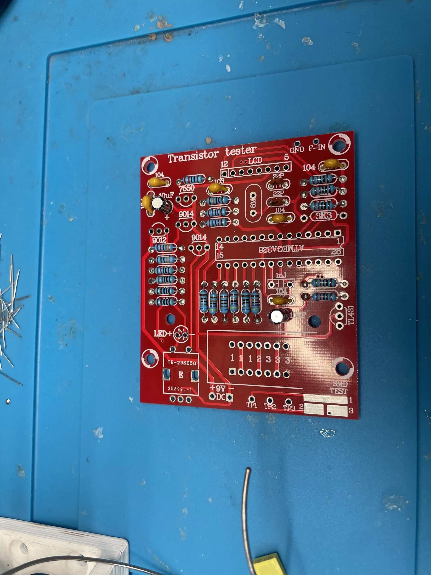
Now add the ceramic capacitors (the small disc/box
parts marked 104, 1nJ, 22p).
These aren’t polarized, so orientation doesn’t matter. The
electrolytic capacitor (10 µF, the small
cylinder) is polarized — match its longer leg /
unmarked side to the + on the silkscreen.
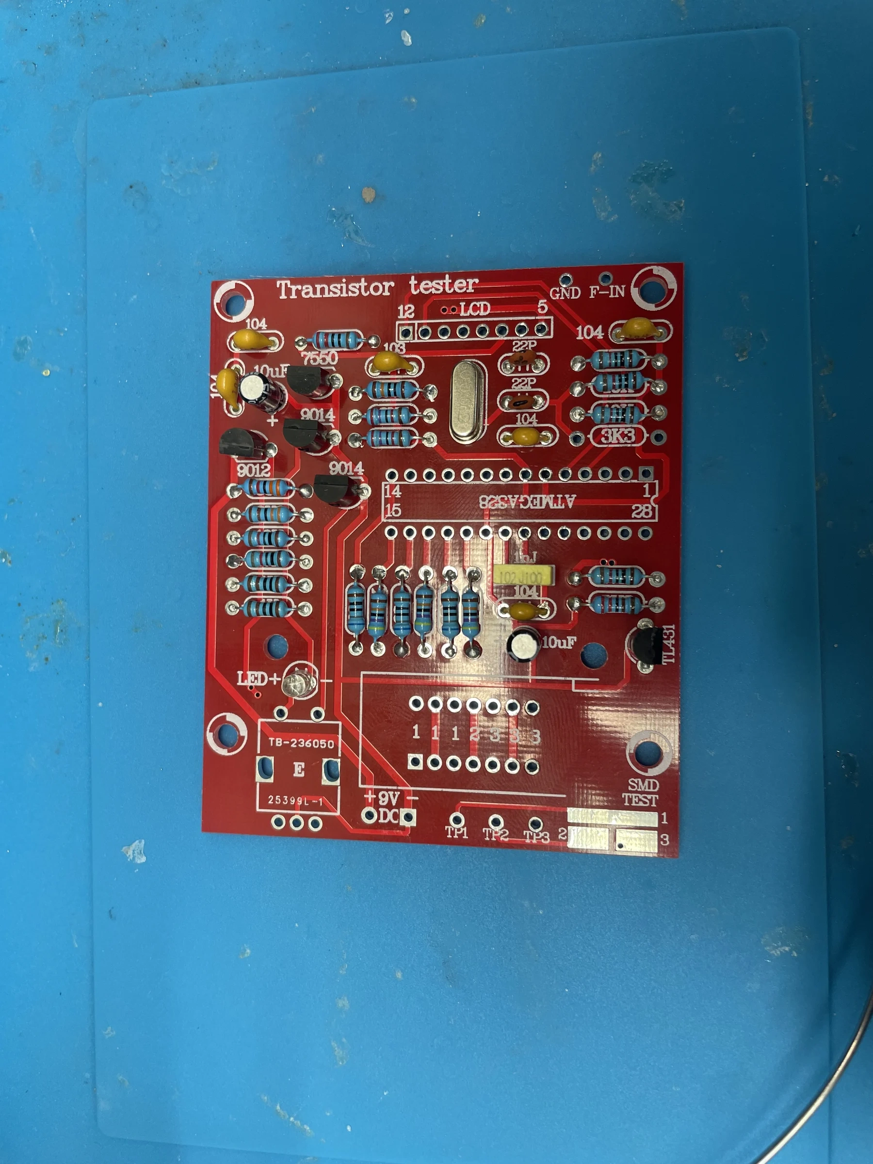
6. Install the semiconductors
Next come the slightly taller parts: the HT7550
regulator, the TL431 reference, the onboard
9012/9014 reference transistors, and the 8 MHz
crystal. Transistors and the regulator are polarized —
match the flat/curved side of each part to the outline printed on the
board.
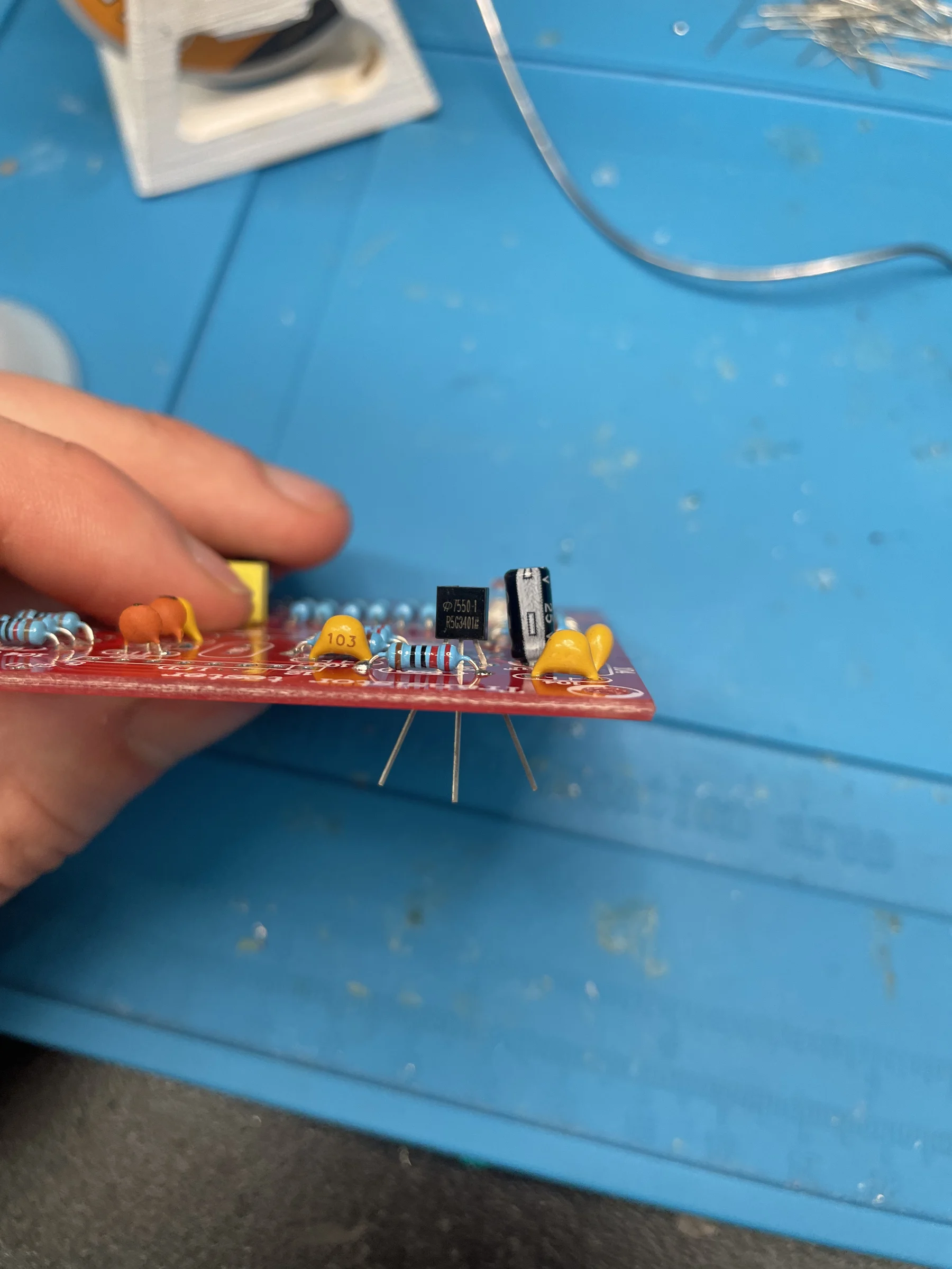
Tip: viewed from the side, you can see parts now stand at different heights — that’s why we go shortest first. Push each part flush before soldering.
7. Install the final components
Home stretch — the tall parts and the bits you don’t want to overheat.
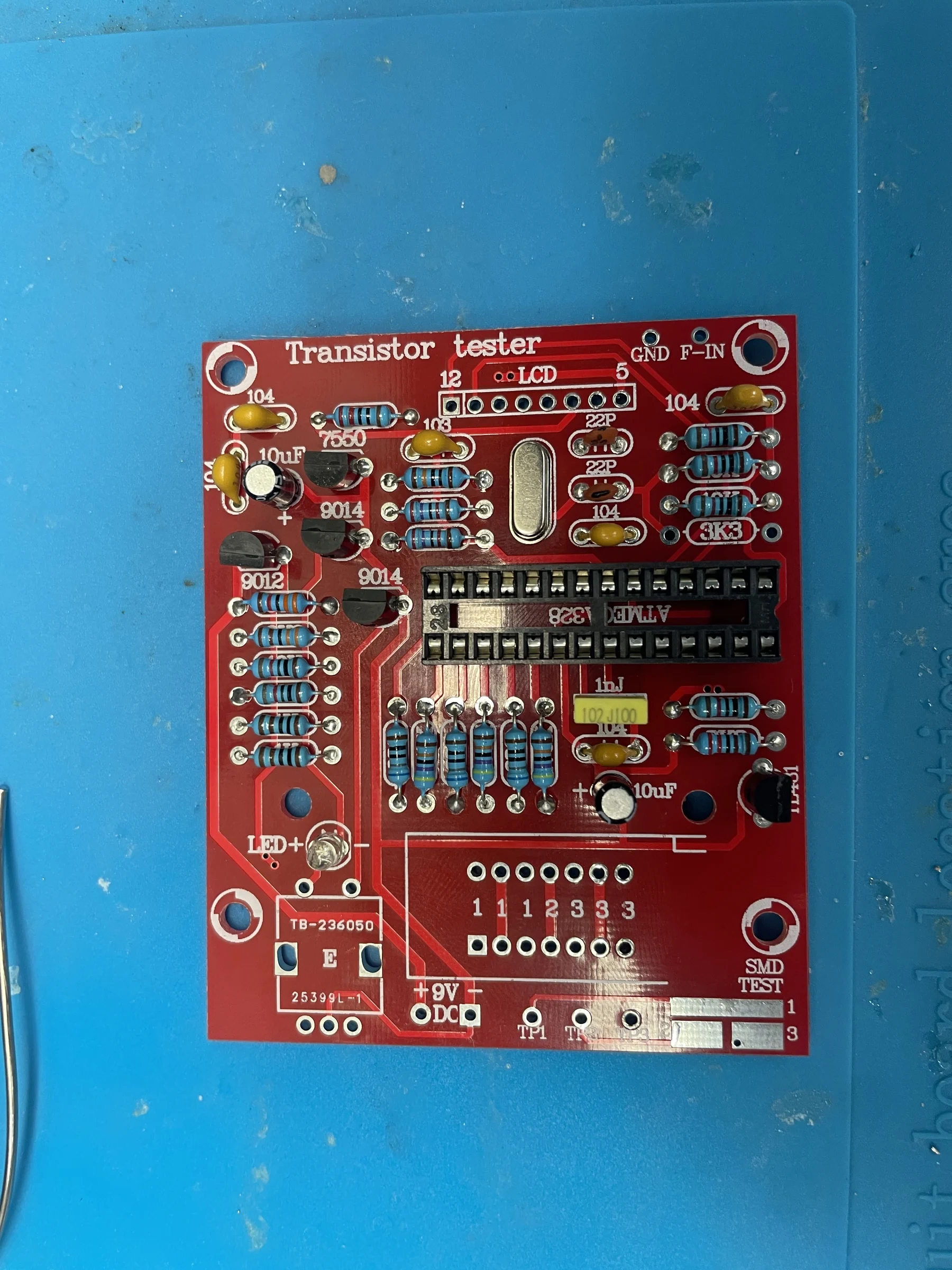
IC socket. Solder the 28-pin DIP socket for the microcontroller (don’t solder the chip directly). Match the notch on the socket to the notch in the silkscreen outline.
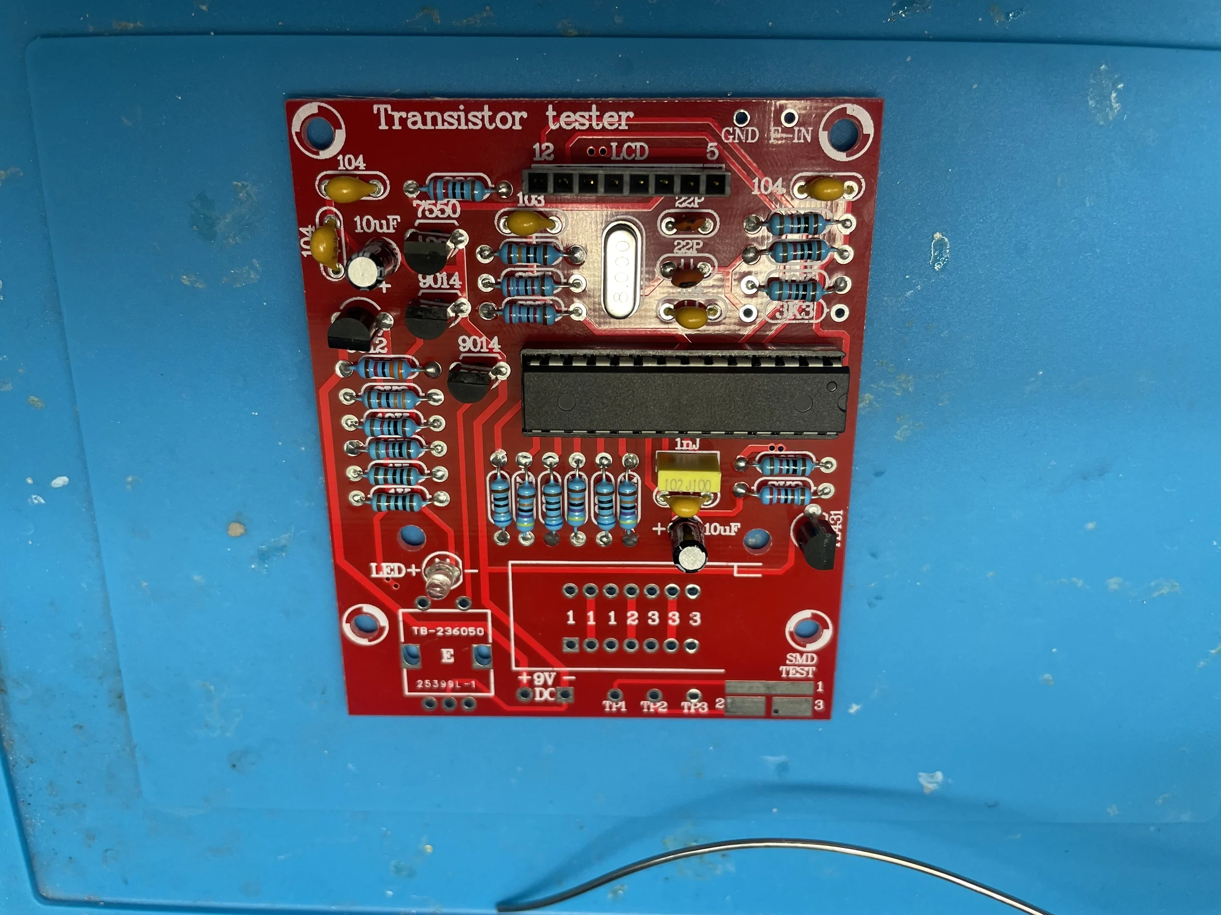
Microcontroller. Once the socket is in, press the ATMEGA328 into it, lining up the notches.
ZIF test socket. This is the lever-action socket you’ll drop components into for testing. Make sure it’s flat against the board before soldering.
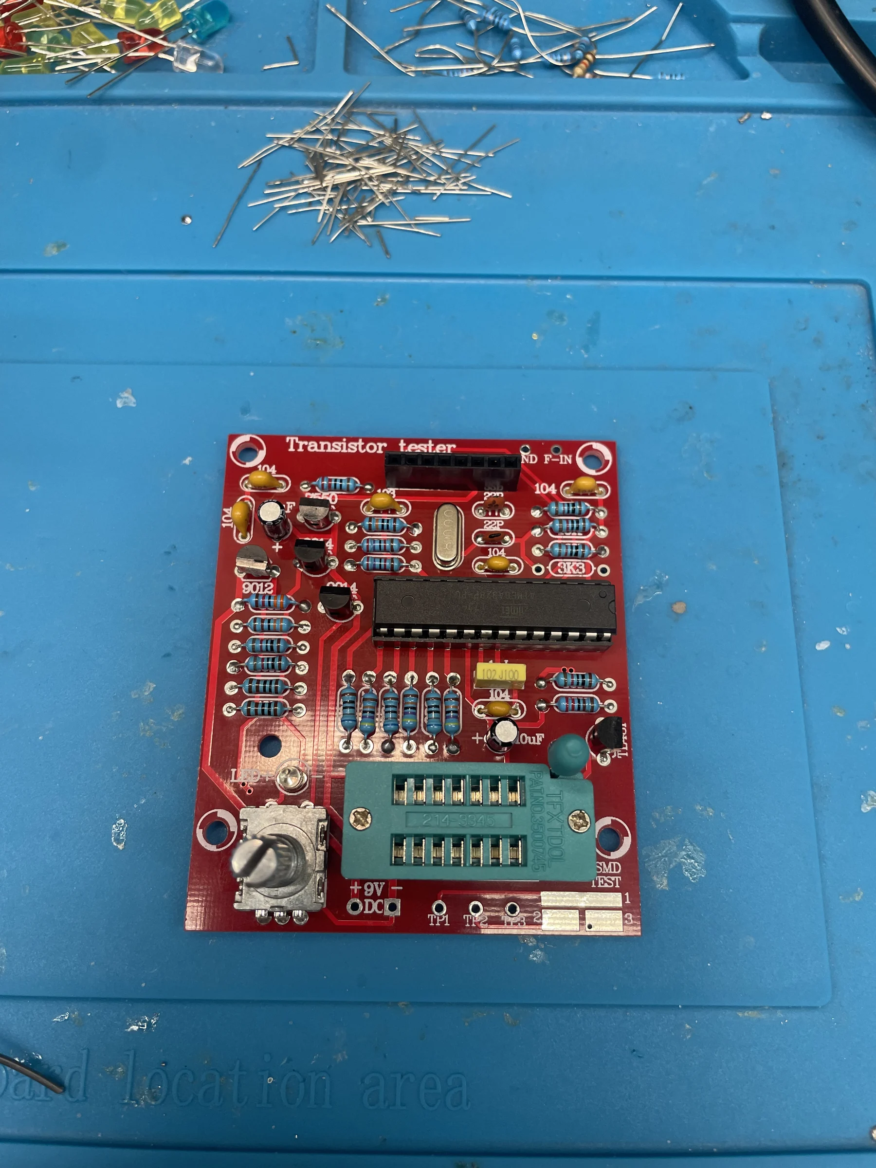
LCD module. The display sits on a pin header. Solder the header to the board, then fit the LCD onto it (or solder the LCD’s pins directly, depending on your kit).
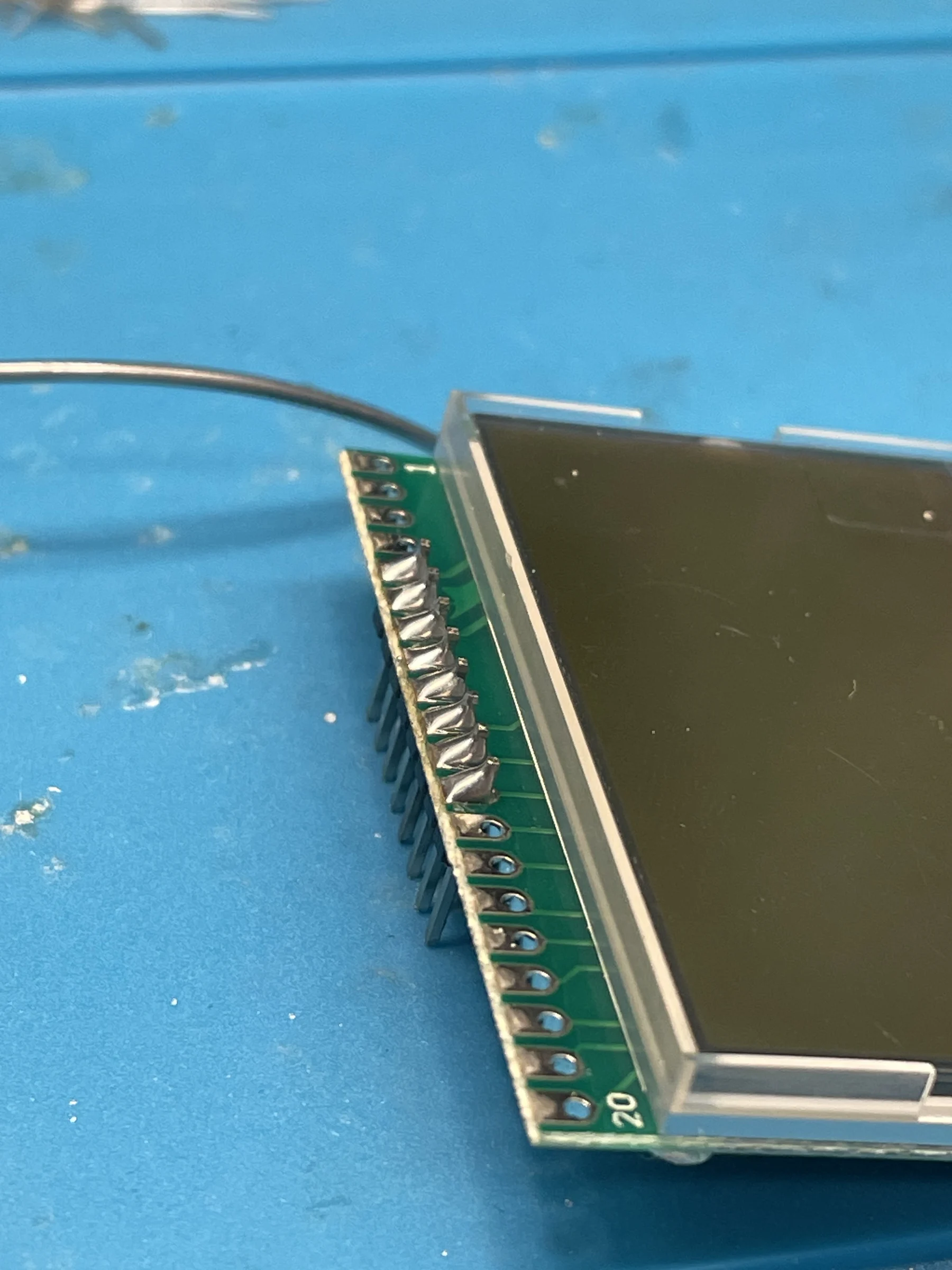
📷 TODO: photo of the LCD mounted on the finished board.
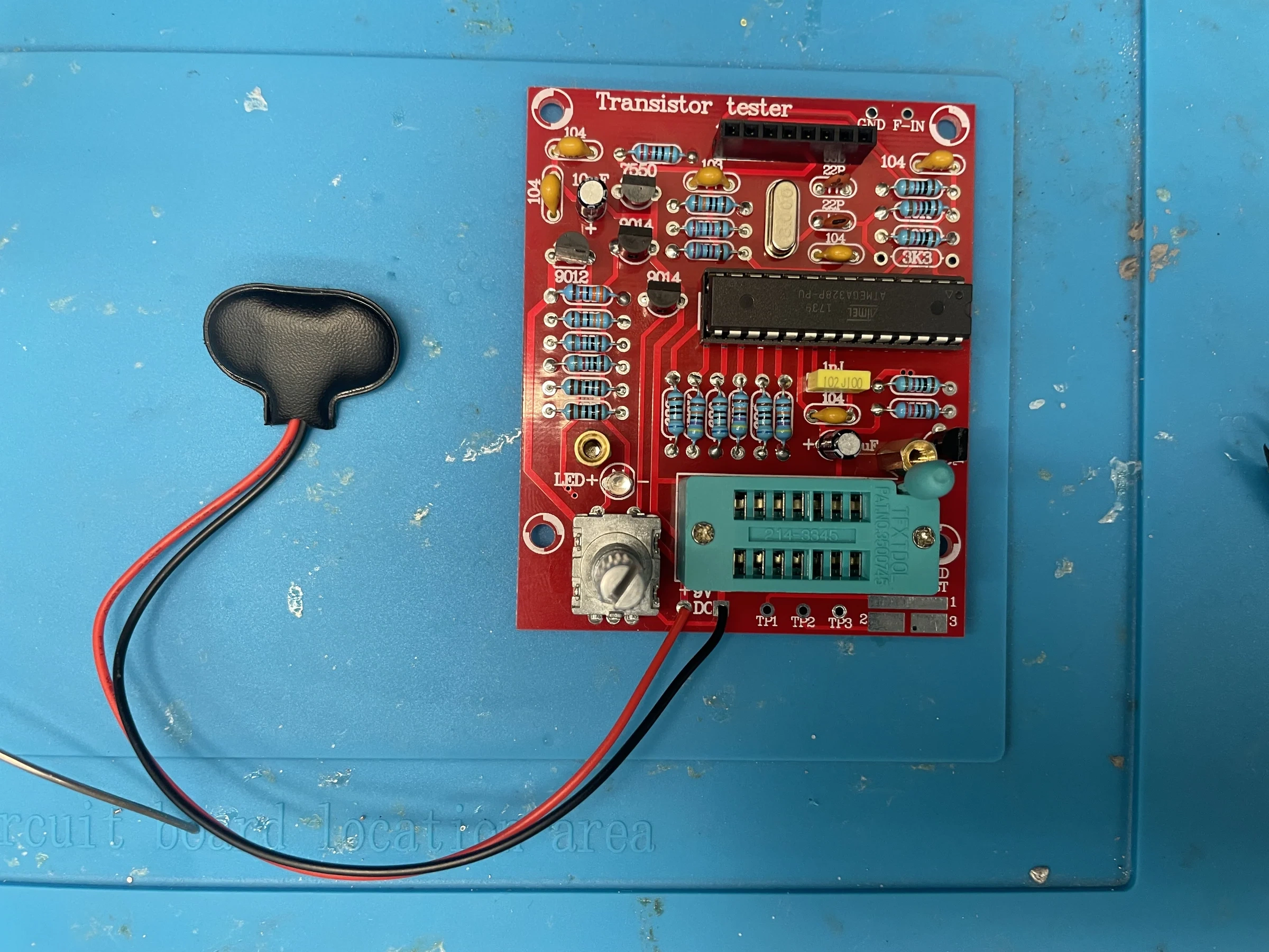
Battery clip. Solder the 9 V battery clip leads last
— red to +, black to – / GND as
marked.
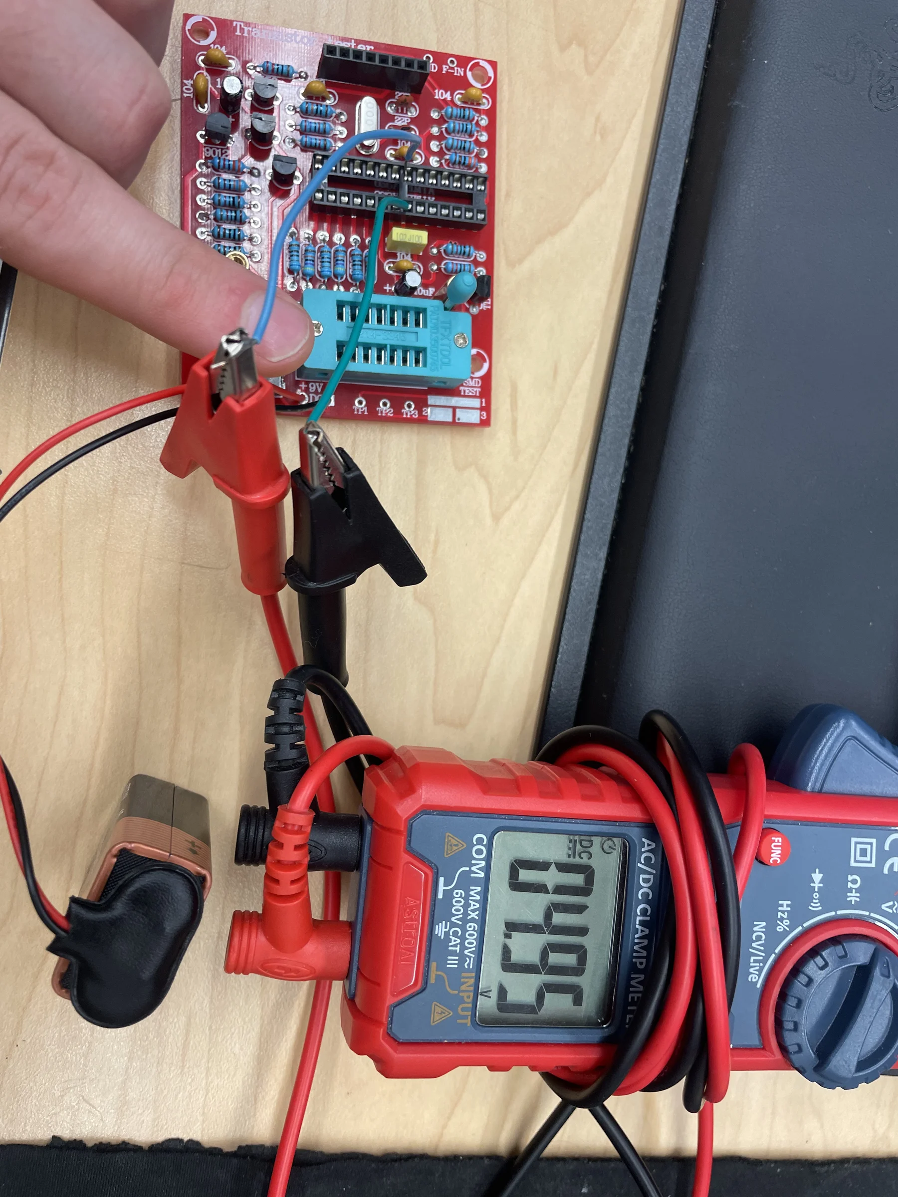
8. Test your work
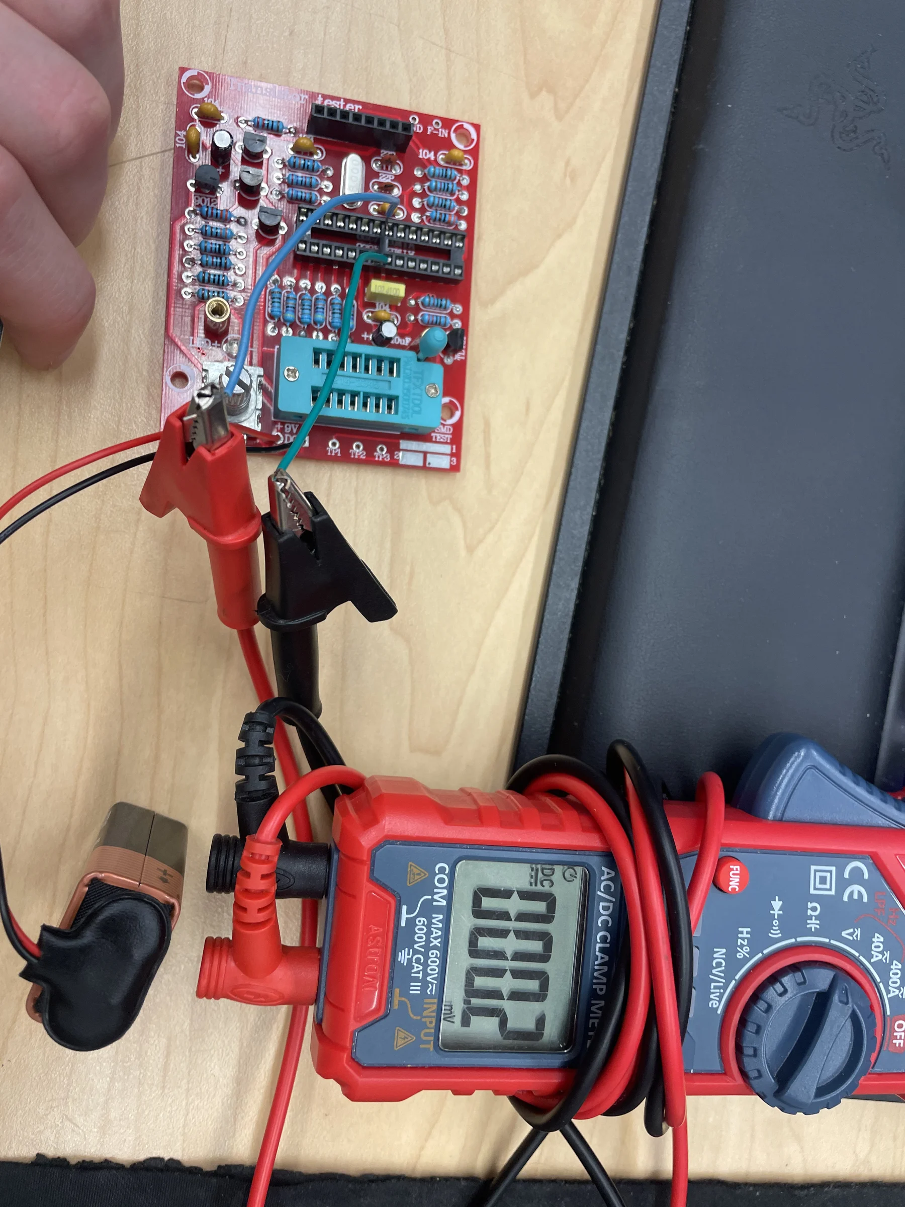
Before powering up, give the board a once-over: look for cold joints
(dull/cracked), solder bridges (blobs connecting two pads that shouldn’t
touch), and missed joints. A multimeter is handy here — check that
there’s no short between the +9V and GND
rails.
9. Finished tester — see it work
Connect a 9 V battery, drop a component (try a resistor or an LED) into the ZIF socket, and press the test button. The LCD should light up and display the measured values.
📷 TODO: add photos of the completed tester powered on and measuring a real component (place them in
assets/09_final_results/).
Optional: a 3D-printed case
A printable enclosure for this board is included in ./case (OpenSCAD source). See its README for details.
Troubleshooting
| Symptom | Likely cause |
|---|---|
| Nothing on the LCD | Battery polarity / dead battery; adjust the contrast trimpot; LCD header not fully soldered |
| Display is blank but backlit | Turn the contrast trimpot |
| Garbled or wrong readings | Cold joint or solder bridge; a resistor in the wrong position |
| Gets warm / battery drains fast | Solder bridge between +9V and GND —
recheck the power rails |
| A component reads “none” / fails | Reseat it in the ZIF socket and clamp the lever firmly |
Most problems on a kit like this come down to a single bad joint. When in doubt, reflow the suspect joints and recheck against the schematic.
New to soldering? Further reading
- “Soldering is Easy” comic — a 7-page illustrated beginner guide (public domain). The best thing to read first.
- Curious Inventor — “How to Solder Correctly… and Why” — step-by-step with the reasoning behind each step, plus lots of good/bad joint photos.
- PACE “Basic Soldering for Electronics” video series — older but thorough; great close-ups of through-hole technique.
- EEVblog soldering tutorial — an approachable hands-on through-hole walkthrough.